Schematic of the sensor locations. [diagram] 3 bar map sensor wiring diagram [diagram] 3 bar map sensor wiring diagram diagram 5.3 sensor locations
Map Sensor Wiring Diagram For Your Needs
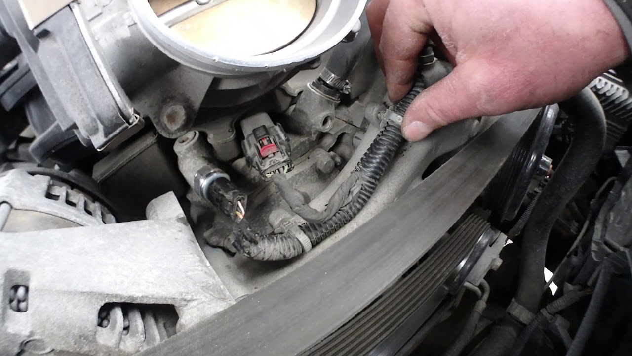
Map sensor wiring diagram 7.3 powerstroke sensor location diagram How to install a 3 bar map sensor
Gxp stock map sensor wiring
Map sensor circuit diagramLs1 map test sensor install bar p0107 dtc diagram wire gm honda pressure gen trouble manifold absolute swap prostreetonline Schematic diagram of the sensors used within the model tests. figura 3️saginomiya dual pressure switch wiring diagram free download| gambr.co.
[diagram] 02 sensor location diagrams[diagram] 3 bar map sensor wiring diagram 3 & 4 pin map sensor wiring diagram: properly wire it upMap sensor wiring diagram for your needs.

[diagram] 02 sensor location diagrams
Gm 3 bar map sensorSensor locations for the three-sensor case Inference diagram of a five sensor, five-component system [2Schematic overview of sensor locations.
Wiring zr1 ls1 maf cimg2 ibsrv corvetteforum 1997Map sensor wiring diagram Understanding the 3 wire sensor diagram: a comprehensive guide5.3 ls sensor diagram.

[solved] draw the schematic diagram of sensor a is tested on the bench
Schematic representation of the 5-sensor experimental setup, includingLs1 maf wiring schematic [diagram] 3 1 engine diagrams sensor locations[diagram] 02 sensor location diagrams.
2014 gmc sierra engine[diagram] 22re engine sensor diagram Block diagram of the 3 × 5 sensor array with detectors of various sizesBased on this diagram, what can you tell about these.

[diagram] 02 sensor location diagrams
Sensor installation location diagram.Solved the block diagram shows a three transducer-sensor 7.3 powerstroke sensor location diagram.
.


![[DIAGRAM] 3 Bar Map Sensor Wiring Diagram - MYDIAGRAM.ONLINE](https://i2.wp.com/www.evolutionm.net/forums/attachments/evo-engine-turbo-drivetrain/142891-need-diagram-stock-map-sensor-pigtail-mdp.jpg)
![[Solved] Draw the schematic diagram of Sensor A is tested on the bench](https://i2.wp.com/www.coursehero.com/qa/attachment/25702406/)
![[DIAGRAM] 3 Bar Map Sensor Wiring Diagram - MYDIAGRAM.ONLINE](https://i2.wp.com/lh5.googleusercontent.com/proxy/J7VDnugw1z3O9V2PltsiGLBDI3CWHyFJ61nkxJC2avwuDnhZZdauzzdBdefTOy9Uxdb3ZXRJqOvK5HeieimWnKCxzGTMbRP3uFd8MLz7MnmdYZqTbDtPfSJ7h9oRyhe9Yd_0uTGHJaN9juQpp0VAWLceXg=s0-d)
![[DIAGRAM] 3 1 Engine Diagrams Sensor Locations - MYDIAGRAM.ONLINE](https://i2.wp.com/www.2carpros.com/images/question_images/69621/original.jpg)